How this job was run Hide the detail
CHALLENGE
Six slabs for six homes in Davenport, 1,250 square feet each — 7,500 square feet of pad in total — and one sequence that has to be right before a single yard of concrete is ordered, because after the pour none of it can be reached again.
Everything that fails in a slab-on-grade fails underneath it. Fill that was never compacted settles, and the slab cracks on a line nobody can predict. A vapor retarder torn at a stub-up feeds ground moisture into the floor for the life of the house, where it surfaces years later as a flooring failure and gets blamed on the flooring. Steel lying flat on the sheeting is steel in the wrong half of the section, doing nothing at all. And on a production subdivision the schedule is not yours: six pads have to reach inspection on the builder’s dates, with the lots on either side being worked at the same time.
The other constraint is the one with people in it. A pad under preparation is a field of vertical steel at shin and chest height, and a fall onto it is the injury that ends a career.
SOLUTION
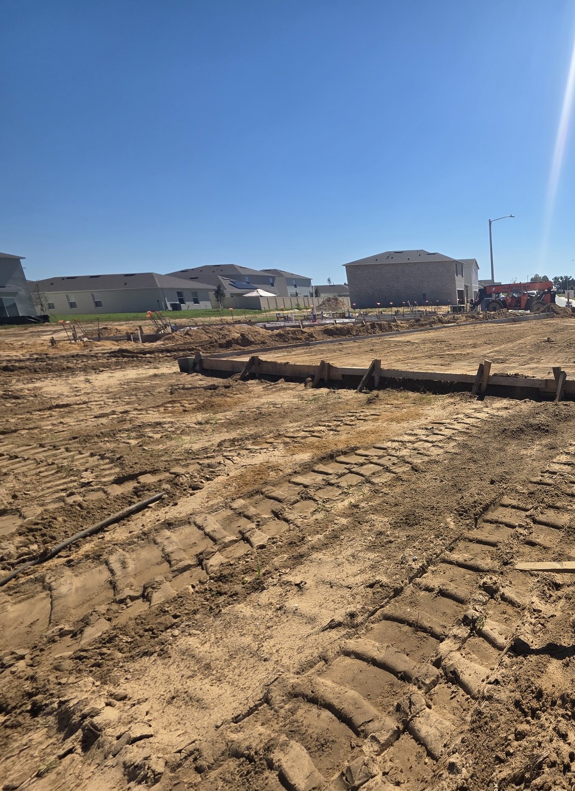
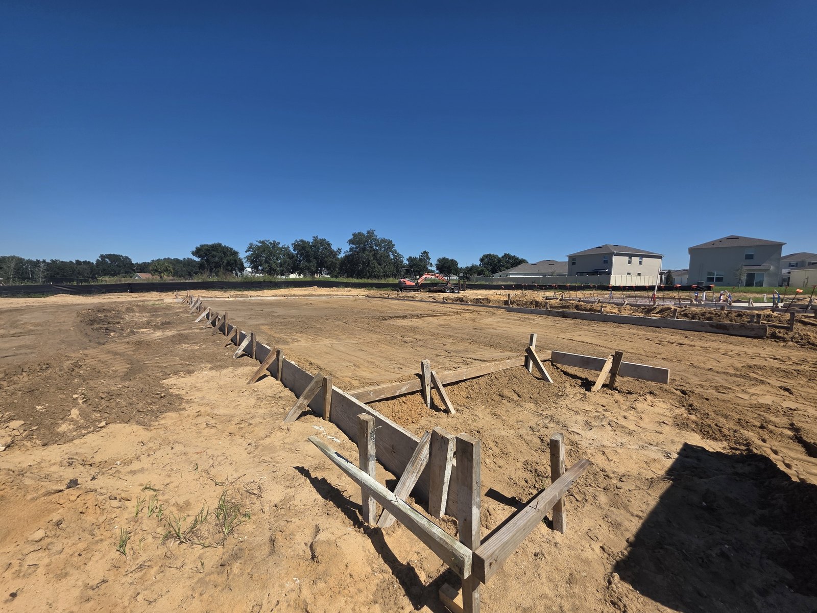
Earthwork first, and it decides the rest. Cut and fill to the elevations on the engineer’s plan, subgrade compacted, pad brought to grade, and the perimeter then excavated for the thickened edge that carries the bearing walls. The pad is proof-rolled before anything is built on it: a soft spot found by a machine costs an hour, and a soft spot found by a finished floor costs a slab.
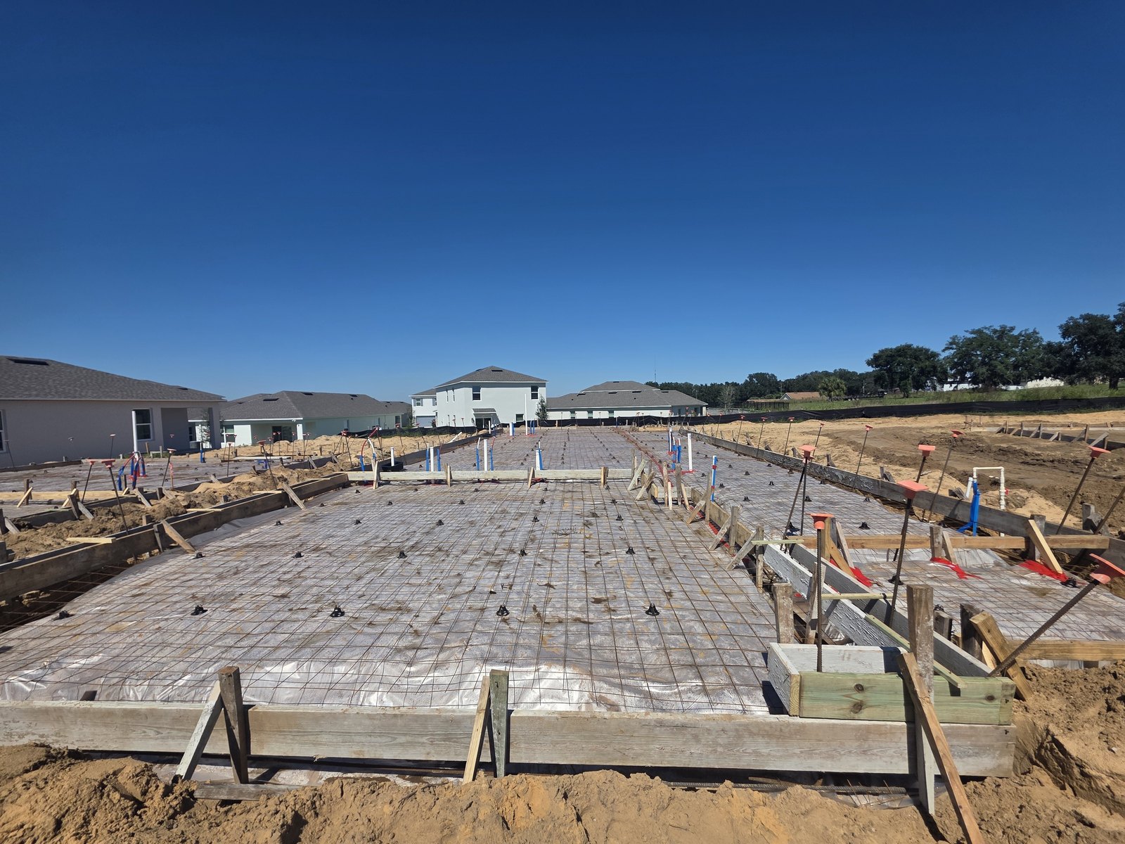
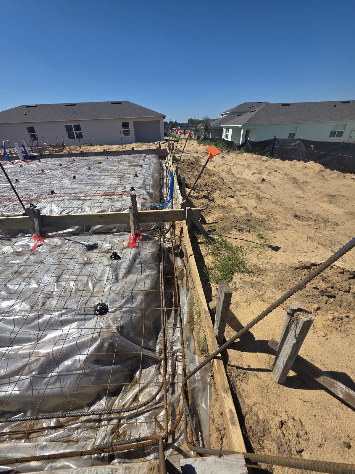
Forms next. Wood form boards set to line and to elevation, staked outside the pour line and braced with kickers so they cannot walk when the concrete goes in. The perimeter is strung and checked square on the diagonals rather than eyeballed off the lot line, because a pad that is out of square is only discovered when the wall plates are being laid out.
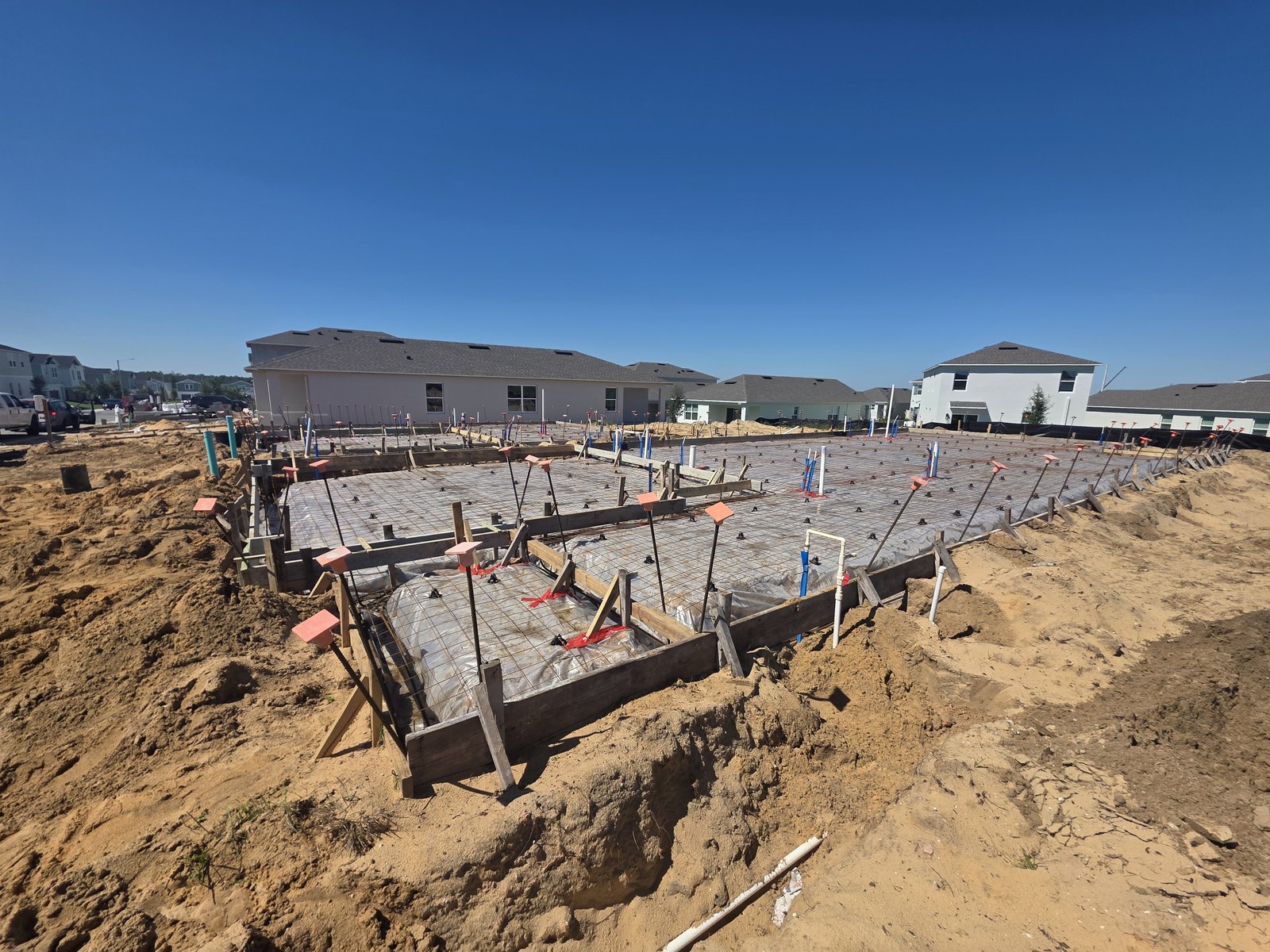
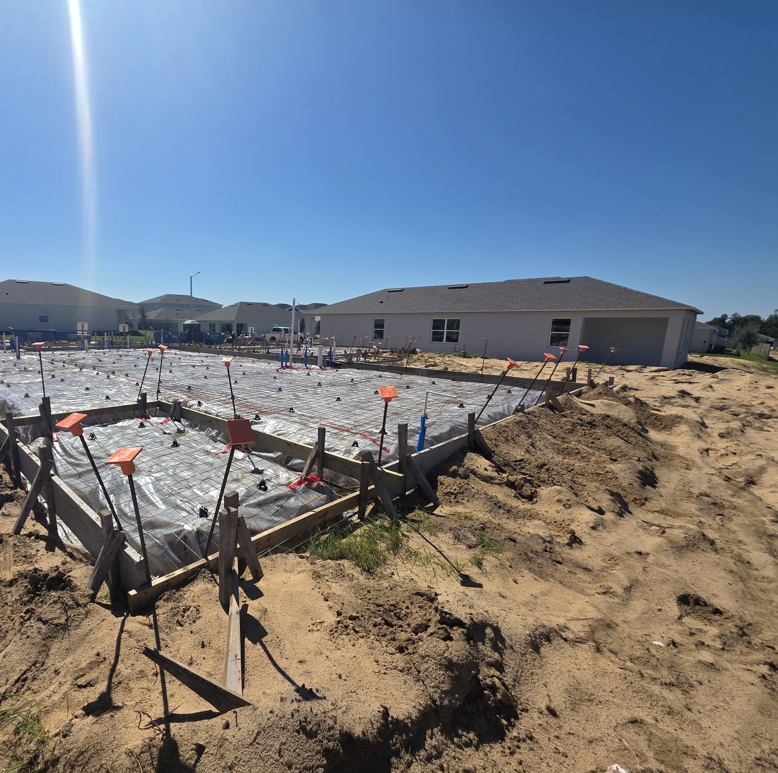
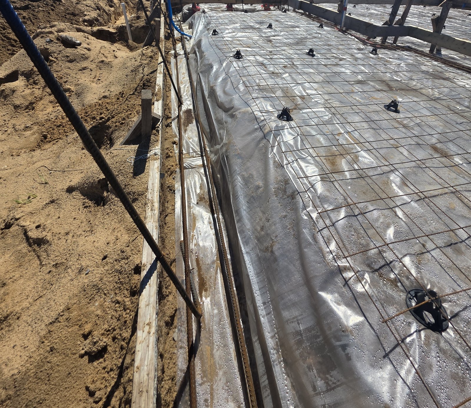
Then the vapor retarder, and here the specification is the work. The sheeting is a plastic water vapor retarder to ASTM E1745 — the standard that sets what the material has to survive under a slab. It caps water vapor permeance at 0.1 perms and then separates Class A, B and C by tensile strength and puncture resistance, A being the toughest and the one normally specified under a house. The class for any given job comes off the drawings, not off whatever roll came on the truck. It is installed to ASTM E1643, the practice that covers the rest: laps of not less than six inches, the sheeting carried up the inside face of the forms and terminated at the slab edge, and every penetration sealed — the plumbing stub-ups and the electrical sleeves that come up through it. A vapor retarder with a hole in it is not doing its job, and every hole it will ever have is made before the pour, not after.
Steel last, and placed rather than dropped. The number that decides this part is cover — the concrete between the bar and the outside world — because that is what keeps the steel passive and out of reach of moisture. It is set by ACI 318, which works by exposure rather than by element: three inches where concrete is cast against and permanently in contact with the ground — the perimeter beam — and three quarters of an inch in a slab that is neither exposed to weather nor in contact with ground. That gap is the reason the bar in the beam is held up off the trench instead of laid in the bottom of it, and the figure that governs each element on a given job is on the structural drawings.
Welded wire reinforcement is laid out, lapped and tied, and carried on bar supports following the practice in ACI 302.1R, so that it sits at the position in the slab depth the drawings call for rather than on the sheeting — and the supports are spaced close enough to hold it there while somebody walks on it and while the concrete goes in, which is the criterion ACI 302.1R actually sets and the half that gets skipped. Reinforcing bar in the perimeter beams, tied, with dowels left standing where the plans show them. All of it set to the structural drawings and left exposed, because the point of this phase is that somebody who did not build it can walk it and read it.
And every vertical bar wears a cap. The orange plastic on top of each stake and dowel in these photographs is impalement protection, and it is not a courtesy: OSHA requires, in 29 CFR 1926.701(b), that all protruding reinforcing steel onto which someone could fall be guarded so that the hazard of impalement is eliminated. A pad under preparation is exactly that — a field of steel at shin and chest height — so every bar is capped, and the caps go on as the steel is placed rather than at the end of the day. It is a large part of why six pads were prepared with zero accidents.
RESULT
Six residential pads in Davenport, Polk County, prepared end to end — 1,250 square feet each, 7,500 square feet in total — and handed over ready for inspection and for concrete. Earthwork, grade, compaction, perimeter excavation, forms set and braced, vapor retarder lapped and sealed, welded wire reinforcement carried on chairs, reinforcing bar and dowels tied to the structural drawings. Zero accidents.
What a builder gets out of this phase is not a slab. It is a pad that somebody else can pour on without finding anything.
Projects